


What are oscilloscopes used for?
An oscilloscope, formerly known as an oscillograph (informally scope, oscope, or o-scope), is a benchtop instrument that graphically displays electrical signals and shows how those signals change over time. They are used by engineers to troubleshoot circuits and check signal quality. Most engineers use a digital oscilloscope, which is what we’re going to focus on here. Digital oscilloscopes acquire and store waveforms, which show a signal’s voltage, frequency, the portion of the signal that is noise, whether the signal is distorted, the timing between signals and more.
But when it comes to choosing the best oscilloscope, how do you know which oscope is right for your application? There are 10 primary factors to consider when you buy an oscilloscope. For a quick overview of the top factors, watch the short video below. Otherwise, keep reading for the full details on how to choose an oscilloscope for your application.
Comparing the Best Oscilloscopes from Tektronix
Top Oscilloscope for Education & Teaching Labs

Offering affordable performance in a compact design, the TBS1000C digital storage oscilloscope provides the features, versatility and durability required by today's educational institutions, embedded designers, and maker community.
| Bandwidth | 50 MHz - 200 MHz |
| Analog Channels | 2 |
| Sample Rate | 1 GS/s |
- 7-inch WVGA color display with 15 horizontal divisions shows 50% more signal
- 32 automated measurements enable fast and convenient testing of a wide variety of signal conditions
- Dual window FFT with simultaneous time and frequency domain views to understand signal frequency content
- Disable autoset cursors and measurements
- Trigger frequency counter
- Pan and zoom capability to quickly see signal details in an area of interest
- Multi-language user interface with support for ten languages in the user interface and front panel overlay
- Small footprint and light weight
- Fanless design for low noise operation
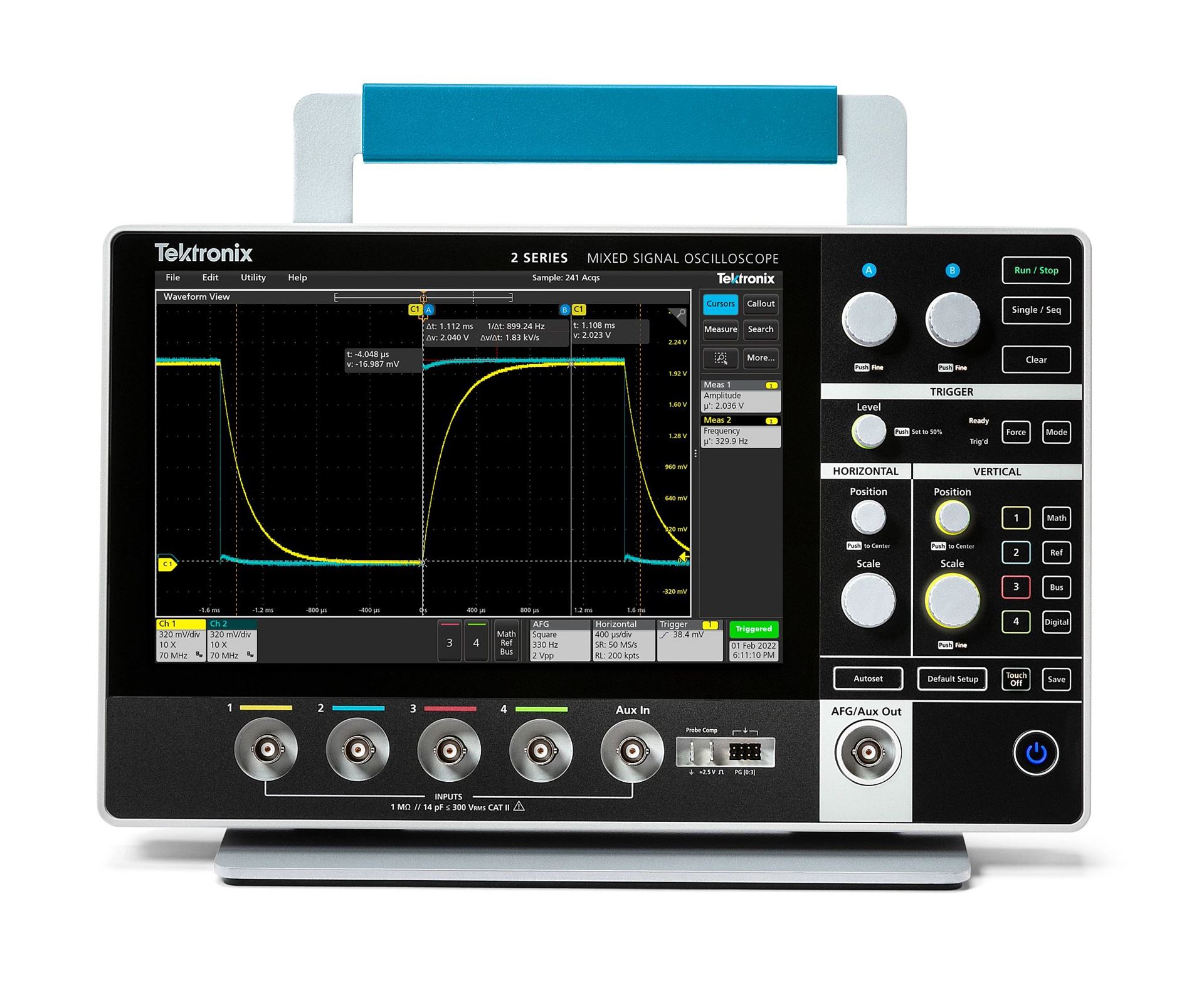
Best Oscilloscope for Portability & Handheld Capability

Unlock more space on your bench without compromising performance. At only 1.5 inches thick and less than 4 pounds, the 2 Series MSO is a full featured, real-time touchscreen oscilloscope in a compact, portable form factor that feels like a tablet. On the benchtop, in the classroom, or to the field, take it wherever your measurement challenges take you.
| Analog Bandwidth | 70 MHz, 100 MHz, 200 MHz, 350 MHz, 500 MHz |
| Analog Channels | 2 or 4 |
| Digital Channels | 16 (optional) |
| Sample Rate | 1.25 GS/s - 2.5 GS/s |
- Optional two-slot battery pack supports up to 8 hours of battery life and can be hot swapped in the field.
- Full suite of capture and analysis capabilities with advanced triggers, search and mark, math and measurements
- Optional 16 channel MSO, 50 MHz, AFG and 4 bit digital pattern generator
- Supports decoding, triggering and analysis for the most common serial protocols
- Industry standard VESA mount for use with various accessories
Oscilloscope Best Designed for Low-Bandwidth RF Analysis (EMI/EMC) & Power Application

With the largest display in class, improved low-level signal measurement accuracy and industry-leading probe performance, the 3 Series MDO sets a new standard for bench oscilloscopes. Whether you’re testing your baseband design for IoT or just for simple EMI sniffing, the 3 Series has a unique true hardware spectrum analyzer built right in with superior RF test performance and guaranteed RF specifications
| Bandwidth | Up to 1 GHz |
| Analog Channels | 2 or 4 |
| Digital Channels | 16 |
| Sample Rate | 2.5 GS/s - 5 GS/s |
- TPP Series probes included standard. One per analog channel.
- Industry-best capacitive probe loading of 3.9 pF
- 250 MHz, 500 MHz or 1 GHz probe bandwidth depending on instrument bandwidth

The versatile 4 Series B MSO has the performance to address tough design challenges and a user interface that works the way you expect. With a new upgraded processor system, it delivers accurate measurements faster with an outstanding range of analysis tools.
| Bandwidth | Up to 1.5 GHz |
| Analog Channels | 4 or 6 |
| Digital Channels | Up to 48 |
| Sample Rate | 6.25 GS/s |
- A new processor system for
- 2X more responsive user interface
- Faster analysis
- Faster data transfers
- New display technology for greater contrast and wider viewing angle
- New annotations indicate key reference levels and times for measurements
- Full support for e*Scope browser-based remote access and control
- 2 new USB 3 host interfaces provide faster data transfers
- Waveform histograms for greater insight into noise and jitter
Best Oscilloscope for Power System Design, Wide Bandgap (WBG), SiC/Gan

Get a complete view of your design with high-fidelity waveforms, insightful measurements, unique spectrum analysis, and flexible probing. Experience the intuitive user interface appreciated by engineers everywhere.
| Bandwidth | Up to 2 GHz |
| Analog Channels | 4, 6 or 8 |
| Digital Channels | Up to 64 |
| Sample Rate | 6.25 GS/s |
- 12-bit resolution at 1.25 GHz; 16-bit resolution at 50 MHz
- Built-in DDCs enable multi-channel, synchronized spectrum analysis
- Results tables, measurement statistics, histograms, and trend plot views
- Support for over 25 serial protocols covering the most common interfaces
- Advanced single-phase and three-phase power analysis packages
- Measurement tools for signal integrity and power integrity
- Optional Windows® operating system lets you run PC software
Top Ranking Oscilloscope for Data, Power, and Advanced Research, Motors, Drives & Inverters (IMDA)

For analyzing and debugging systems with GHz clock and bus speeds, the 6 Series B MSO provides the best signal fidelity with the lowest input noise and up to 10 GHz analog bandwidth. With its intuitive touchscreen user interface, a 15.6-inch high definition display and FlexChannel™ inputs, the 6 Series is a high-performance instrument that’s also a pleasure to use.
| Bandwidth | 1 GHz, 2.5 GHz, 4 GHz, 6 GHz, 8 GHz, 10 GHz |
|
Digital Channels |
Up to 64 (optional) |
|
Input Channels |
4, 6 or 8 |
| Sample Rate | Up to 50 GS/s |
- 15.6 inch, HD capacitive touch display delivers unmatched signal visibility
- 4 FlexChannel™ inputs can each handle 1 analog or 8 digital signals
- Lowest noise at high sensitivity
- >70% noise reduction from previous generation oscilloscopes
- 12-bit Analog-to-digital converters with enhanced resolution up to 16 bits
Best Oscilloscope Engineered for High-Performance, Mil/Gov, Advanced Communications

Whether you’re at first power-up on your latest design, verifying compliance to the fastest standards, or researching fundamentals of the universe, these oscilloscopes deliver the performance, precision, and tools to get your job done faster.
| Analog Bandwidth | 8 GHz–33 GHz |
| Analog + Digital Channels | 4 (DPO), 4 + 16 (MSO) |
| Sample Rate (2/4 Channels) | 100/50 GS/s |
- 8 to 33 GHz true analog bandwidth for measurements on the latest high-speed serial standards.
- 100 GS/s sample rate on 2 channels.
- 16 logic channels with 80 ps timing resolution for debug of digital and analog signals (MSO70000 models).
- iCapture - One connection for analog and digital signals (MSO70000 models).
- Fastest waveform capture rate with >300,000 wfms/s maximum.
Quickly determine which oscilloscope you need using “the Rule of Five”
Bandwidth
System bandwidth determines an oscilloscope's ability to measure an analog signal - the maximum frequency range that it can accurately measure.
- Rule of five: The bandwidth of the scope, together with the probe, should be at least 5x the maximum signal bandwidth for better than ±2% measurement error.
- Example: Scopes with a maximum bandwidth of 100 MHz can accurately (within 2%) show the amplitudes of sine-wave signals up to 20 MHz.
- Caution: If bandwidth is too low, your oscilloscope will not resolve high-frequency changes. Amplitude will be distorted. Edges will vanish. Details will be lost.
Rise Time
While analog engineers look at bandwidth, digital engineers are more interested in the rise time of signals like pulses and steps. The faster the rise time, the more accurate are the critical details of fast transitions.
- Rule of five: An oscilloscope's rise time should be < 1/5 x fastest rise time of signal
- Example: A 4-ns rise time needs a scope with faster than 800 ps rise time. (As with bandwidth, achieving this rule of thumb may not always be possible).
- Caution: To slow a rise time for the circuit being tested could shift the pulse in time and give a wrong value.
Sample Rate
The sample rate of an oscilloscope is similar to the frame rate of a movie camera. It determines how much waveform details the scope can capture. Sample rate (samples per second, S/s) is how often an oscilloscope samples.
- Rule of five: Use a sample rate of at least 5x your circuit's highest frequency.
- Example: Oscilloscopes come with a wide variety of sample rates, from 1 to 200 GS/s, all to suit your application and the type of signal you wish to capture.
- Caution: The faster you sample, the less information you'll lose and the better the scope will represent the signal under test. But the faster you will fill up your memory too, which limits the time you can capture.

10 Factors to Consider When Choosing an Oscilloscope
Oscilloscope bandwidth
System bandwidth determines an oscilloscope’s ability to measure a signal. Specifically it determines the maximum frequency that the instrument can accurately measure. Bandwidth is also a key determining factor in the oscilloscope price.

By using the ‘Five Time Rule’ you can determine the bandwidth that you need. The bandwidth of the scope, together with the probe, should be at least 5x the maximum signal bandwidth for better than +/- 2% measurement error.
The probe and oscilloscope form a measurement system that has an overall bandwidth. Using a low-bandwidth probe will lower the overall bandwidth, so be sure to use probes that are matched to the scope.
For example, a 100 MHz oscilloscope is usually guaranteed to have less than 30% attenuation at 100 MHz. To ensure better than 2% amplitude accuracy, inputs should be lower than 20 MHz. For digital signals, measuring rise and fall time is key. Bandwidth, along with sample rate, determines the smallest rise-time that an oscilloscope can measure.
Oscilloscope rise time
Rise time describes the useful frequency range of an oscilloscope, and this is a critical measurement in the digital world. Rise time is often considered when measuring digital signals like pulses and steps.

In order to accurately capture the details of rapid transitions, an oscilloscope must have sufficient rise time. Fast rise time is also needed for accurate time measurements. To calculate the oscilloscope rise time required for your signal type, use this equation:

For instance, a 4-ns rise time needs a scope with faster than 800 ps rise time. Note: As with bandwidth, achieving this rule of thumb may not always be possible. Many logic families have faster rise times (edge speeds) than their clock rates suggest. A processor with a 20 MHz clock may well have signals with rise times similar to those of an 800 MHz processor. Rise times are critical for studying square waves and pulses.
Oscilloscope sample rate

The sample rate of an oscilloscope is similar to the frame rate of a movie camera. It determines how much waveform detail the scope can capture.
Sample rate (samples per second, S/s) is how often an oscilloscope samples the signal. Use a sample rate of at least 5x your circuit’s highest frequency component. Oscilloscopes come with a wide variety of sample rates, from 1 to 200 GS/s, to meet the needs of your application.
The faster you sample, the less information you’ll lose and the better the scope will represent the signal under test. However, fast sampling will also fill up your memory quickly, which limits the time you can capture.
Channel density of an oscilloscope
Digital oscilloscopes sample analog channels to store and display them. In general, the more channels the better, although adding channels adds to the oscilloscope price.

Your application will determine whether you need to choose an oscilloscope with two, four, six, or even eight analog channels. Two channels let you compare a component’s input to its output, for example. Four analog channels let you compare more signals and provides more flexibility to combine channels mathematically (multiplying to get power, or subtracting for differential signals, for example). Oscilloscopes with six or eight channels allows for multiple bus analysis while simultaneously viewing voltage or current type signals in a power related environment.
A Mixed Signal Oscilloscope adds digital timing channels, which indicate high or low states and can be displayed together as a bus waveform. Whatever you choose, all channels should have good range, linearity, gain accuracy, flatness, and resistance to static discharge.
Some instruments share the sampling system between channels to save money. But beware: the number of channels you turn on can reduce the sample rate.
Compatible oscilloscope probes
Good measurements begin at the probe tip. The scope and probe work together as a system, so be sure to consider probes when selecting an oscilloscope.
When taking measurements, probes actually become a part of the circuit, introducing resistive, capacitive, and inductive loading that alters the measurement. To minimize the effect, it’s best to use probes that are designed for use with your scope.
Select passive probes that have sufficient bandwidth. The probe’s bandwidth should match that of the oscilloscope.
A broad range of compatible probes will allow you to use your scope in more applications. Check to see what’s available for the scope before you buy.

Passive probes: Probes with 10X attenuation present a controlled impedance and capacitance to your circuit, and are suitable for most ground-referenced measurements. They are included with most oscilloscopes – you’ll need one for each input channel.
High-voltage differential probes: Differential probes allow a ground-referenced oscilloscope to take safe, accurate floating and differential measurements. Every lab should have at least one.
Logic probes: Logic probes deliver digital signals to the front end of a Mixed Signal Oscilloscope. They include “flying leads” with accessories designed to connect to small test points on a circuit board.
Current Probes: Adding a current probe enables the scope to measure current, of course, but it also enables it to calculate and display instantaneous power.
Need help choosing the right probe? See our Probe Selector Guide
Triggering capabilities of an oscilloscope
All oscilloscopes provide edge triggering, and most offer pulse width triggering. To acquire anomalies and make best use of the scope’s record length, look for a scope that offers advanced triggering on more challenging signals.

The wider the range of trigger options available the more versatile the scope (and the faster you get to the root cause of a problem):
- Digital/pulse triggers: pulse width, runt pulse, rise/fall time, setup-and-hold
- Logic triggering
- Serial data triggers: embedded system designs use both serial (I2C, SPI,CAN/ LIN…) and parallel buses.
- Video triggering
Oscilloscope record Length
Record length is the number of points in a complete waveform record. A scope can store only a limited number of samples so, in general, the greater the record length, the better.
Time captured = record length/sample rate. So, with a record length of 1 Mpoints and a sample rate of 250 MS/sec, the oscilloscope will capture 4 ms. Today’s scopes allow you to select the record length to optimize the level of detail needed for your application.
A good basic scope for example will store over 2,000 points, which is more than enough for a stable sine-wave signal (needing perhaps 500 points), whilst more advanced high-end scopes would have up to 1Gpoints, which is essential for working with high-speed serial data type applications.
Oscilloscope waveform capture rate
Waveform capture rate, expressed as waveforms per second (wfms/s), refers to how quickly an oscilloscope acquires waveforms. The waveform capture rates of oscilloscopes vary greatly, so it’s important to find the right one for your application.
Oscilloscopes with high waveform capture rates provide significantly more visual insight into signal behavior, and dramatically increase the probability that the oscilloscope will quickly capture transient anomalies such as jitter, runt pulses, glitches and transition errors.
Digital storage oscilloscopes (DSO) employ a serial processing architecture to capture from 10 to 5,000 wfms/s. Some DSOs provide a special mode that bursts multiple captures into long memory, temporarily delivering higher waveform capture rates followed by long processing dead times that reduce the probability of capturing rare, intermittent events.
Most digital phosphor oscilloscopes (DPO) employ a parallel processing architecture to deliver vastly greater waveform capture rates. Some DPOs can acquire millions of waveforms in just seconds, significantly increasing the probability of capturing intermittent and elusive events and allowing you to see the problems in your signal more quickly.
Oscilloscope expandability
As your needs change, you want an oscilloscope that can accommodate your needs with application modules and software updates.
If you want to expand the capabilities of your oscilloscope over time, make sure your instrument has everything you need. For instance, some oscilloscopes allow you to:
- Add memory to channels to analyze longer record lengths
- Add application-specific measurement capabilities
- Complement the power of the oscilloscope with a full range of probes and modules
- Work with popular third-party analysis and productivity
- Windows-compatible software
- Add accessories, such as battery packs and rack mounts
Connectivity of an oscilloscope
After you’ve analyzed your oscilloscope measurements, you’ll need to document and share your findings. The connectivity of an oscilloscope delivers advanced analysis capabilities and simplifies the documentation and sharing of results.
Depending on the oscilloscope, you may have access to standard interfaces (GPIB, RS-232, USB, and Ethernet), network communication modules, or advanced features that allow you to:
- Create, edit and share documents on the oscilloscope, all while working with the instrument in your particular environment
- Access network printing and file sharing resources
- Access the Windows® desktop
- Run third-party analysis and documentation software
- Link to networks
- Access the Internet
- Send and receive e-mail
Need help choosing an oscilloscope? Download our oscilloscope selector guide or contact the experts at Tektronix to request a demo. If you already have a sense of which oscilloscope to buy, shop Tektronix oscilloscopes today.
Learn how to set up Military Standard 1553 serial bus decode with this helpful FAQ guide.
