


Contact us


Call us at
Available 6:00 AM – 5:00 PM (PST) Business Days
Download
Download Manuals, Datasheets, Software and more:
Feedback
Accelerating EV Traction Inverter Analysis
Traction inverters and motors are at the heart of the EV powertrain. Efficiency improvements within these subsystems translate directly into better range, performance, and cost of the vehicle.
Adoption of SiC power semiconductors is contributing to better efficiency and more compact traction inverters. Control algorithms and motor construction are being optimized to achieve demanding efficiency and cost targets
EV architects are combining new traction inverter designs with different motor designs, creating new hybrid structures uniquely suited to the demands of electric mobility.
Learn how to:
- Traction Inverter and Motor Technology
- Analyzing Critical Inverter Signals
- Understanding System Behavior Under Changing Motor Loads
- Visibility into Vector Control Parameters such as DQ0
- Correlating Mechanical and Electrical Measurements
- Understand the Impact of Wide Bandgap Power Device Integration
- EV Traction Inverter and Motor Reference System
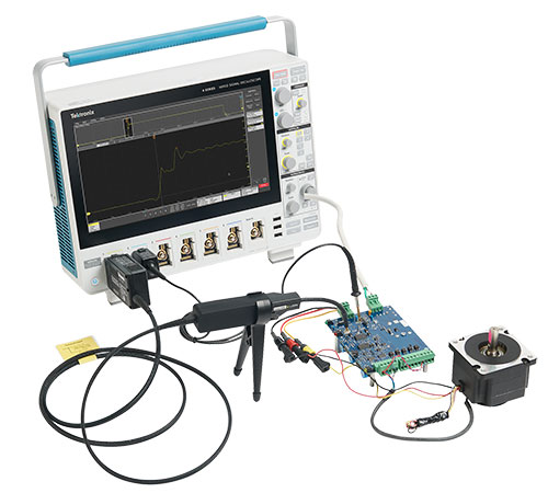
Techniques for Repeatable Inverter Measurements

Functional blocks of a traction inverter and motor.
Traction Inverter and Motor Technology
EVs employ different types of electric motors but they all require the application of PWM voltage signals to the motor stator to develop three sinusoidal currents spaced 120° apart. The modulation of the high-voltage input is usually performed by high-voltage IGBTs or MOSFETs switching at frequencies ranging from 20 to 100 kHz. Designers work hard to minimize energy loss during switching while maintaining safe timing.
Gate drivers are controlled by a microcontroller (MCU) subsystem and determine the timing of the switching devices. The control circuits must be galvanically isolated from the high-voltage sections.
Inverter controllers often use DSP algorithms, such as field-oriented control (FOC), to precisely vary the PWM output. Based on the driver's input and current speed of the motor, the inverter’s MCU controls the angle between the poles of the direct axis of the rotor (D) and the magnetic field, or quadrature axis (Q) to deliver smooth, optimal torque. Sensors such as encoders or resolvers on the motor’s rotor provide feedback on rotor angle.
Analyzing Critical Inverter Signals
Pulse-width modulation and multi-phase current and voltage waveforms have historically presented challenges for automotive oscilloscopes and the engineers who rely on them. Yet being able to see and measure these waveforms is critical to optimizing an inverter’s reliability, robustness, power density and efficiency.
The introduction of 6 and 8-channel oscilloscopes has made it much easier to study 3-phase systems, but for inverters special measurement techniques are also needed:
- PWM signals are difficult to trigger on – making it hard to get stable, repeatable measurements. Special attention must be paid to ensure a stable time reference.
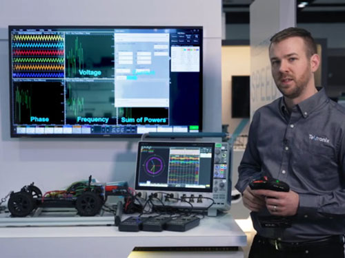
- Analyzing 3-phase systems requires voltage, current, angle and power measurements for individual phases as well as the total system. Phasor diagrams are ideal for observing magnitudes, angles and balance.
Inverter, Motor and Drive Analysis software on 4/5/6 Series oscilloscopes simplifies triggering on PWM outputs and setting up 3-phase measurements. Phasor diagram displays help you visually understand and debug 3-phase electrical problems.

3-phase voltage, current and power measurements on an inverter output.
Learn More:
Learn more about using Phasor Diagrams on Oscilloscopes for 3-Phase Power Analysis

Plots of power parameters over 100 acquisitions, including VRMS, IRMS, true power, phase difference, apparent power and reactive power.
Learn More:
Understanding System Behavior Under Changing Motor Loads
In the quest for power density and efficiency, it is important to understand and analyze the dynamic performance of the drive and motor under many different test conditions including:
- Motor startup
- Different motor loads
- Motor stop
Test times can vary from a few seconds to several minutes depending on the test plan. An oscilloscope with long record length stores all of the relevant information during the run and presents the results as waveforms and plots. Capturing high-speed data gives the engineer an ability to zoom into a particular region of the waveform to pinpoint a problem. In contrast, power analyzers typically support calibrated 3-phase measurements, but without access to high sample rate data.
Visibility into Vector Control Parameters such as DQ0
Closed loop inverter and motor systems use feedback to provide superior control of speed and torque compared to open loop systems. Closed loop “vector” controllers perform real-time computations to transform angular and current feedback into simpler variables (D and Q) which can be linearly scaled in real time. The scaled D and Q parameters are then inverse-transformed to provide input to the modulators used to drive the switches.
Since these important calculations occur deep within the controller, it is difficult to study D and Q in relation to other system parameters. The IMDA application on the 5/6 Series B MSOs supports a unique measurement – DQ0 (Direct Quadrature Zero) that helps engineers gain insight into controllers. It mathematically computes D and Q from the inverter’s output waveforms by applying a combination of Park’s and Clarke’s transform. The results are displayed as numeric measurements and as a phasor diagram with a resultant vector. By incorporating encoder angle, engineers can observe DQ0 vectors aligned with rotor magnet zero position when used with the QEI index pulse. These visual tools provide unique visibility into controller performance during actual operation of the motor.

DQ0 measurements use output waveforms to calculate and display control system coefficients.
Learn More:
DQ0 Analysis of Motor Control Systems Using an Oscilloscope Whitepaper

Acquisition trends and histograms indicate speed variation. Hall sensors are one of the sensor types supported.
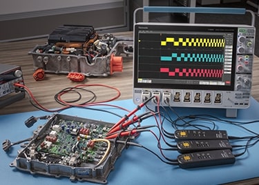
Correlating Mechanical and Electrical Measurements
In order to understand the effects of decisions in electronics and algorithms, engineers must be able to correlate the motor’s mechanical performance with electrical measurements. The motor’s angle, direction, speed, acceleration and torque are key to understanding system performance. Being able to measure both electrical parameters at the input of the traction inverter and the mechanical output of the motor enables engineers to determine overall system efficiency.
Mechanical measurements like speed, direction and angle depend on sensor signals which must be decoded and displayed by the test equipment. Many BLDC motors come equipped with built-in Hall sensors which can be accessed using digital or analog probes. Other systems may rely on QEI (Quadrature Encoder Interface) sensors.
Torque measurements may be performed using a special-purpose torque sensor on the output of the motor. Torque may also be approximated by applying a scale factor to rms current.
With Tektronix IMDA software sensor signals can be decoded, enabling 5 and 6 Series B MSO oscilloscopes to display speed, acceleration, direction, angle and torque.
Understand the Impact of Wide Bandgap Power Device Integration
The transition to 800 V architectures is unlocking benefits such as lower cable and battery costs, reduced thermal loss and higher system efficiency. SiC MOSFETs are enabling higher switching voltages and lower switching loss, but traditional test plans based on silicon devices no longer apply.
Key challenges in testing wide bandgap semiconductors include:
- Current and voltage probing at high power levels
- Accurately measuring signals on high-side MOSFETs in the presence of very high common mode voltages
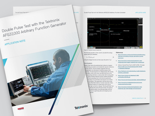
- Measuring switching loss with standardized tests such as double pulse tests
Tektronix provides solutions for testing traction inverters based on SiC MOSFETs including oscilloscopes, high voltage differential probes, current probes, optically isolated probes, signal sources and precision power supplies.

Double pulse testing software uses consistent automated measurement techniques for Eon and Eoff measurements.
Learn More:

EV Traction Inverter and Motor Reference System
Testing an EV Powertrain design requires an oscilloscope, appropriate probes, signal source, and application software. This system may be customized to suit your application.
This traction inverter test system is available as SOLN-IMDA-EV.
| Instrument/Probe/Option | Quantity | Description |
| MSO58B-BW1000* | 1 | 1 GHz, 8 Channel Scope |
| 5-PRO-AUTOMOTIVE-3Y | 1 | Automotive Solution Bundle including Inverter, Motor and Drive Software Analysis Options 5-IMDA, 5-IMDA-DQ0 and 5-IMDA-MECH and decoding for automotive serial buses |
| THDP0200 | 3 | 200 MHz, +/-750 V, high voltage differential probe |
| TCP0030A | 3 | 120 MHz, 30 Arms, spilt-core AC/DC current probe |
| TLP058 | 1 | 8-channel logic probe |
| TEKSCOPE-ULTIMATE | 1 | TekScope PC Software for off-line analysis, including IMDA Analysis and comprehensive serial bus support |
| TEKDRIVE-STARTER | 1 | TekDrive Data Storage Subscription, Individual Tier, Annual user license |
Resources
Frequently Asked Questions (FAQ)
What is a traction inverter and its role in an electric vehicle?
A traction inverter converts the DC power from an electric vehicle's battery into AC power for the electric motor. It controls the motor's speed, torque, and direction, crucial for vehicle movement and efficiency.
What are the main parameters tested in a traction inverter?
Critical parameters include output voltage and current waveform quality, switching frequency, efficiency, thermal performance, electromagnetic interference (EMI), and response to various load conditions.
How is efficiency testing conducted for traction inverters?
Efficiency testing involves measuring input and output power under different load conditions. Efficiency is calculated as the ratio of output power to input power and helps optimize the inverter's energy conversion. Being able to measure both electrical parameters at the input of the traction inverter and the mechanical output of the motor enables engineers to determine overall system efficiency.
What is EMI testing, and why is it essential?
Electromagnetic interference (EMI) testing assesses the inverter's impact on nearby electronics. It ensures compliance with regulatory standards and prevents interference that could affect the vehicle's electronics or other systems.
How are thermal performance and reliability evaluated?
Thermal testing involves subjecting the inverter to high loads and monitoring temperature changes. This simulates real-world conditions and ensures the inverter can handle sustained operation without overheating.
What tools are used for testing of traction inverters?
Oscilloscopes, probes and special analysis software are common tools. They capture waveforms, measure electrical characteristics, monitor temperature, and assess electromagnetic emissions.
How do oscilloscopes assist in traction inverter and motor analysis?
Tektronix high-performance oscilloscope solution enables fast and accurate analysis of the complex and dynamic PWM output of traction inverters, assisting engineers in optimizing traction system efficiency and reliability. Increase your system performance and lower your time-to-market with:
- 3-phase PWM analysis software including electrical, mechanical, system efficiency and DQ0 measurements. Sensors supported: Hall, QEI and Resolver
- Oscilloscopes Time Trend plot for analyzing motor start up profile
- Serial protocol decoding for common vehicle protocols like CAN, LIN, and SENT
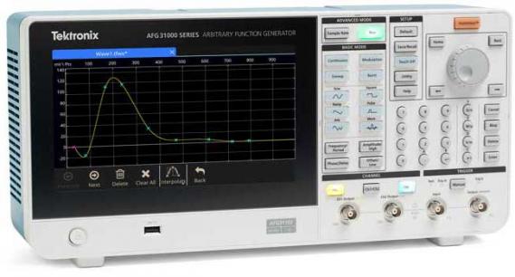
- Arbitrary Function Generator for injecting signals
- PC-based remote control for operating at a safe distance from high-voltage and rotating devices
- IMDA solution offers two unique trend plots on the power quality measurement to support such requirements: Time trend plot and Acq trend plot.
- Acq (Acquisition) trend plots record specific dynamic measurements as motor parameters change over multiple acquisitions.
- Supports mathematical conversion of Line-Line to Line-Neutral for specific wiring. This is useful when true neutral wiring or probing to this is difficult.
- Analyze Inverter and Automotive three-phase designs for DC input and AC output wiring configuration.
- Configure wiring(s) and filters to perform efficiency measurements for a DC-AC topology most suitable for inverter testing.
Why IMDA is an important debug and analysis tool for designers and validation engineers?
IMDA helps engineers design better and more efficient three-phase motor drive systems, taking full advantage of the advanced user interface, six or eight analog input channels, and ‘High Res’ mode (up to 16 bits) on the 5 Series/5 Series B/6 Series B MSO.