

- User interface designed for both touch and mouse
- Large touchscreen HD displays (1,920 × 1,080)
- Integrated spectrum analysis
- Powerful analysis
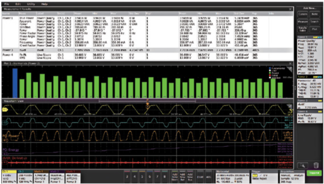
- Automated measurements with trend, histogram, and spectrum plots
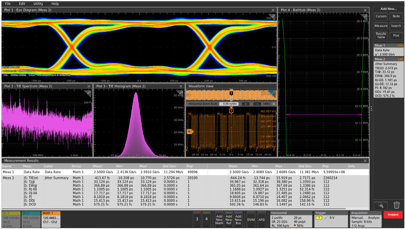
- Advanced jitter analysis
- Power measurement options
- User-defined filter creation
- Bandwidth
- Models from 100 MHz to 10 GHz
- All models offer upgradeable bandwidth
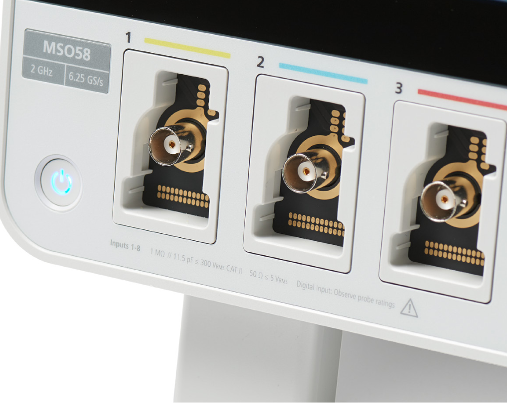
- Input channels
- 2 to 8 inputs depending on model
- Low-loading probes included for each channel
- Built in Arbitrary/Function Generator option
- Record length
- 10 Mpoints to 1 Gpoints depending on model
- Up to 12-bit vertical resolution (up to 16 bits in High Res mode)
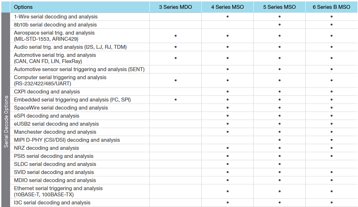
- Protocol options
- 1-Wire, 8b10b, Automotive Ethernet, CAN / CAN FD, CXPI, eSPI, Ethernet, eUSB2, FlexRay, I2C / SPI, I2S Audio, I3C, LIN, Manchester, MDIO, MIL-STD-1533 / ARINC 429, MIPI CSI/DSI, NRZ, PSI5, RS-232 / UART, SDLC, SENT, SpaceWire, SPMI, SVID, USB 2.0
- Integrated DVM and trigger frequency counter free with product registration
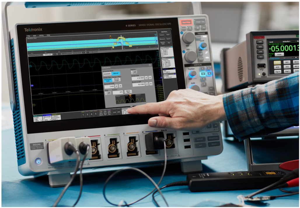
Touch Interaction Done Right
These next-generation oscilloscopes feature the industry’s first oscilloscope user interface truly designed for touch. The same intuitive gestures you use with your phone or tablet, work on the big HD displays and the gestures are common among the 3, 4, 5 and 6 Series.
- Control inputs, triggers and acquisitions by tapping badges in the settings bar at the bottom of the display
- Drag waveforms to adjust position or to pan
- Pinch to change horizontal or vertical scale
3, 4, 5, 6
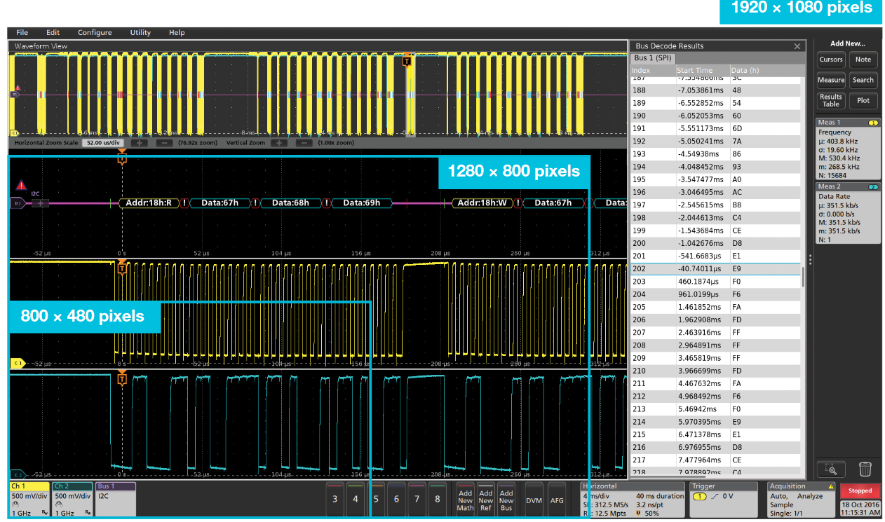
Stunning HD Displays
The 15.6" displays on 5 and 6 Series MSOs have 1920 × 1080 HD resolution. You can see many signals at once, along with critical readouts and plots for an extensive view of your system.
Even with their bench-friendly footprints, the 3 and 4 Series offer the largest displays in their classes, with full 1920 × 1080 HD resolution.
3, 4, 5, 6
Performance and Measurements
More Inputs and Mixed Signal Analysis
The 4, 5 and 6 Series MSOs let you see more signals by going beyond the traditional 4-channel limit, offering up to 8 analog input channels.
FlexChannel® inputs on the 4, 5, and 6 Series MSOs expand your visibility even further. Whenever you need to see more signals, just plug a TLP058 logic probe into any input. The single analog channel converts to 8 digital channels. FlexChannel inputs are backwardcompatible with TekVPI probes.
The 3 Series MDO offers 16 digital channels through a dedicated logic probe, included with the MSO option.
3, 4, 5, 6
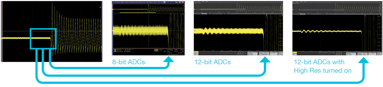
Industry-leading Vertical Resolution
See more signal detail. The 4, 5, and 6 Series MSOs feature 12-bit analog-to-digital converters (ADCs) that provide 16 times more vertical resolution than common 8-bit ADCs.
A new High Res mode further boosts vertical resolution and uses smart filtering to limit noise. High Res mode always provides at least 12 bits and extends all the way to 16 bits of vertical resolution.
4, 5, 6
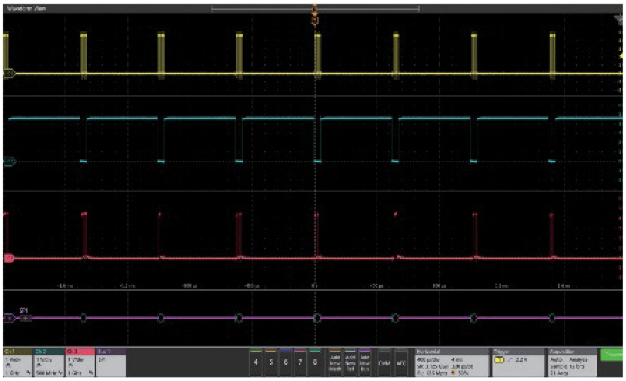
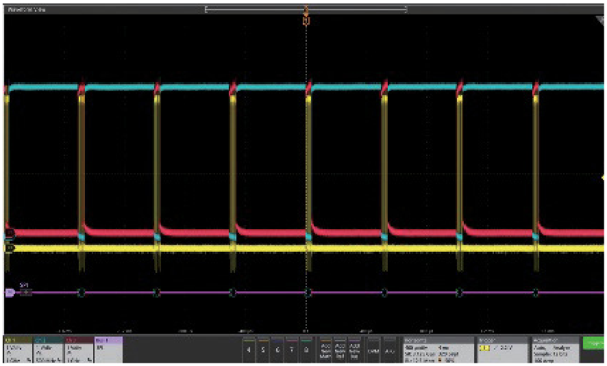
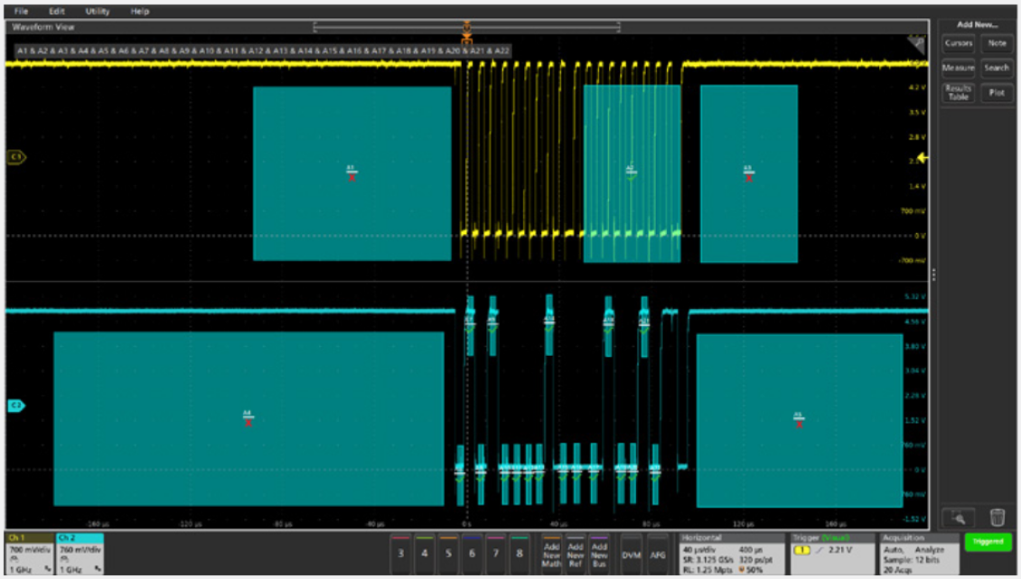
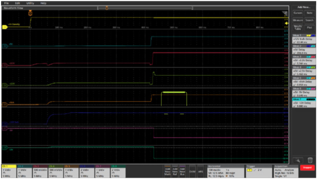
Stacked Display Mode
Most scopes display all waveforms in the same graticule and rely on vertical scale controls to fit signals on the display. Each waveform uses a fraction of the available ADC range, leading to less accurate measurements.
New stacked display mode lets you view each waveform in its own “slice” of the display. Each slice represents the full ADC range for the waveform for more accurate measurements.
The more traditional overlay display mode is also available, for easy direct comparison of waveforms.
4, 5, 6
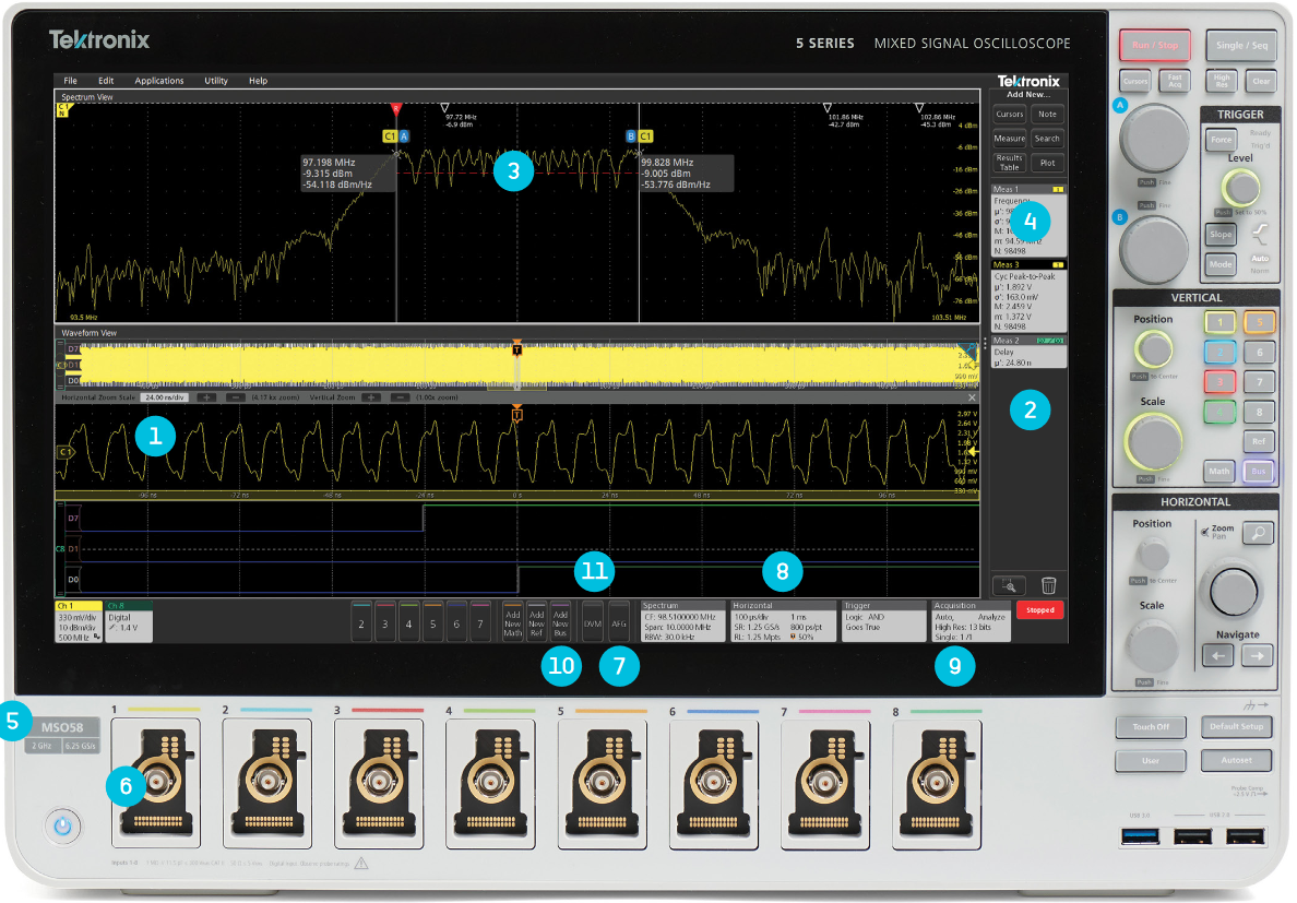
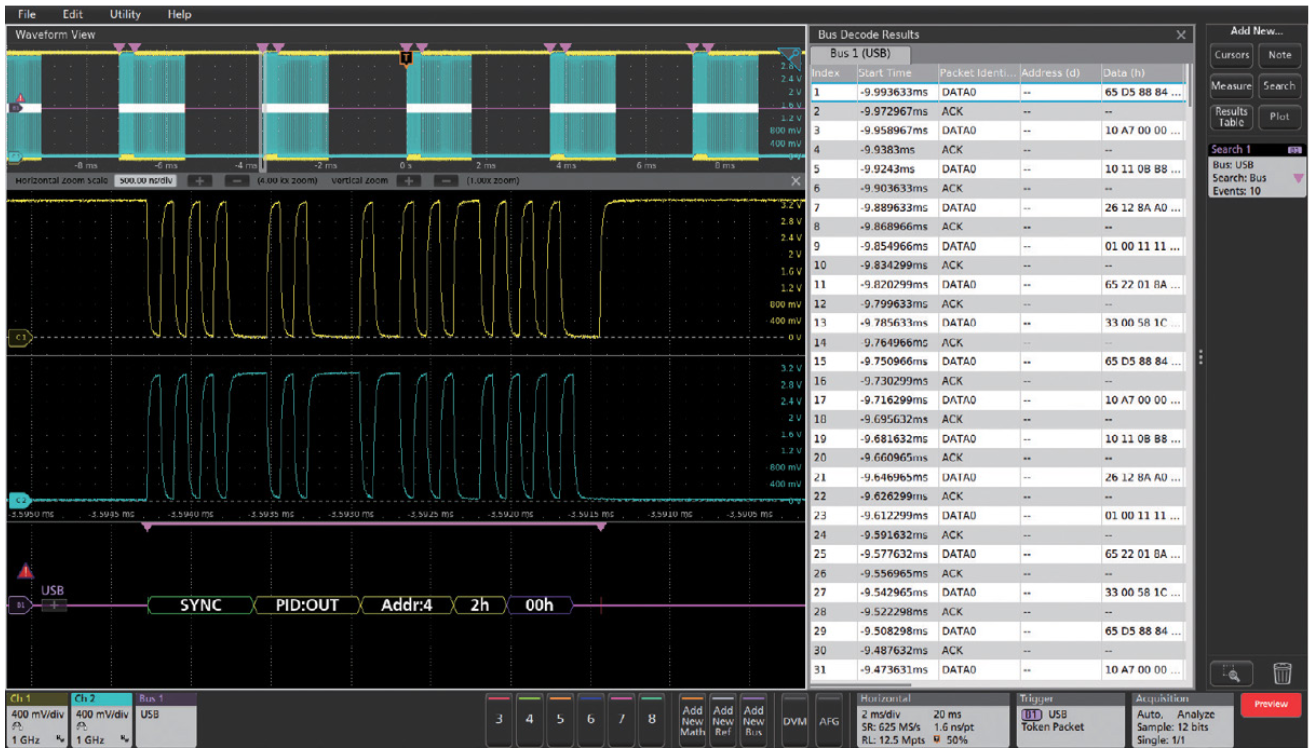
Powerful Measurements
The Results Bar on the right side of the display includes immediate, one tap access to the most common analytical tools such as:
- Cursors
- Automated measurements
- Measurement statistics
- Searches
- Bus decode tables
These scopes deliver rich insights by providing easy access to measurement statistics. Turn on statistics in the Results Bar to get a quick overview.
3, 4, 5, 6
Advanced Measurements and Analysis
Dive into measurements with Results Tables. Results Tables show statistics for the current acquisition and for all acquisitions. Get insight into one measurement, a hundred measurements, or millions of measurements at a glance.
Plots, such as measurement trends and histograms, deliver quick insight.
4, 5, 6
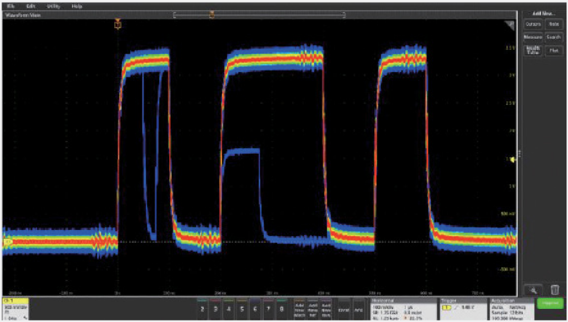
FastAcq™ High Speed Waveform Capture
FastAcq captures at high speed to increase the probability of seeing infrequent problems such as runt pulses, glitches, timing issues, and more.
3, 4, 5, 6
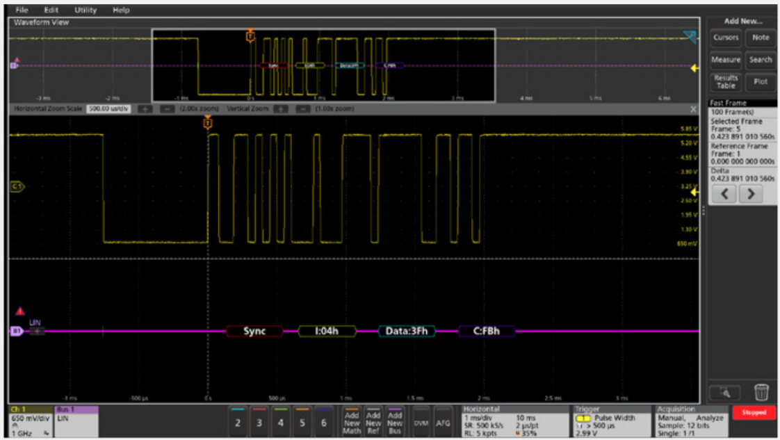
FastFrame™ Segmented Memory
Make the most efficient use of acquisition memory by not storing deadtime between serial packets or bursts. Capture many triggered frames in a single record.
3, 4, 5, 6
Triggering and Search
A complete set of basic and advanced triggers and search criteria.
- Runt
- Logic
- Pulse width
- Timeout
- Rise/Fall time
- Setup and hold violations
- Serial and parallel bus activity
- Sequence
- Video
- Visual triggers*
- RF vs Time*
- Window*
3, 4, 5, 6
An Oscilloscope for Every Engineer


Integrated Spectrum Analysis
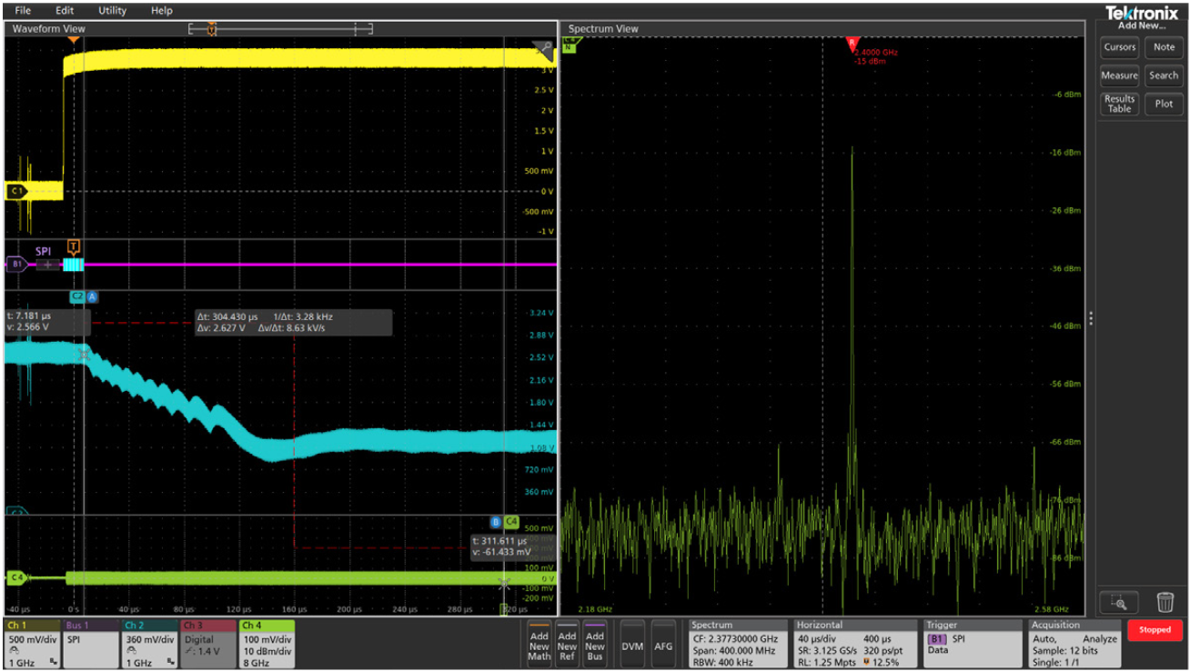
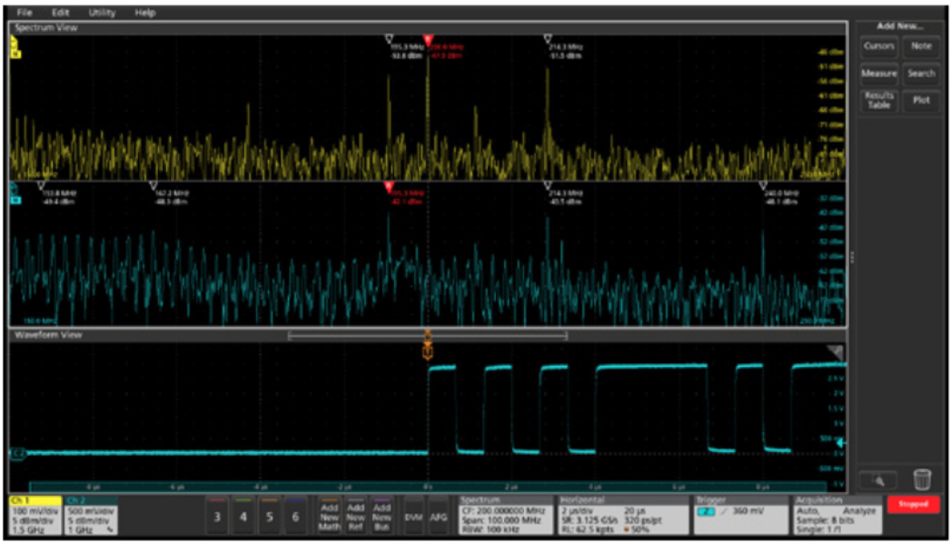
Spectrum View
Because traditional scope FFTs are driven by the same acquisition system that delivers the analog time-domain view, it is virtually impossible to get optimized views in both domains at once.
Spectrum View is different. It lets you independently adjust time- and frequency-domain views, by using patented technology behind each FlexChannel input. You can turn on a spectrum view for any analog channel, enabling multi-channel mixed domain analysis.
Intuitive spectrum analyzer controls like center frequency, span and resolution bandwidth (RBW) make setups easy, and RF vs time triggers make capturing anomalies straightforward.
4, 5, 6
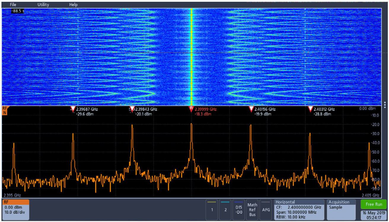
Built-in Spectrum Analyzer
The Tektronix 3 Series MDO offers an integrated, hardware-based spectrum analyzer ranging from 9 kHz to 1 GHz (standard) or 3 GHz enabling spectral analysis on IoT and most consumer wireless standards.
3
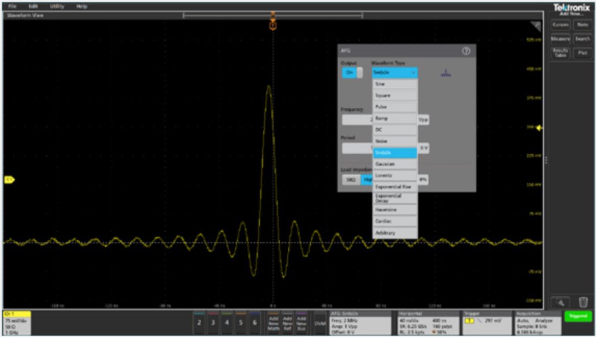
Built-in Arbitrary/Function Generator (AFG)
An integrated function generator is perfect for testing frequency response, simulating sensor signals, and adding noise to signals for stress testing.
- 13 standard waveform functions
- 50 MHz Sine / 25 MHz Square and Pulse
- 128k, 250 MS/s arbitrary waveforms
3, 4, 5, 6
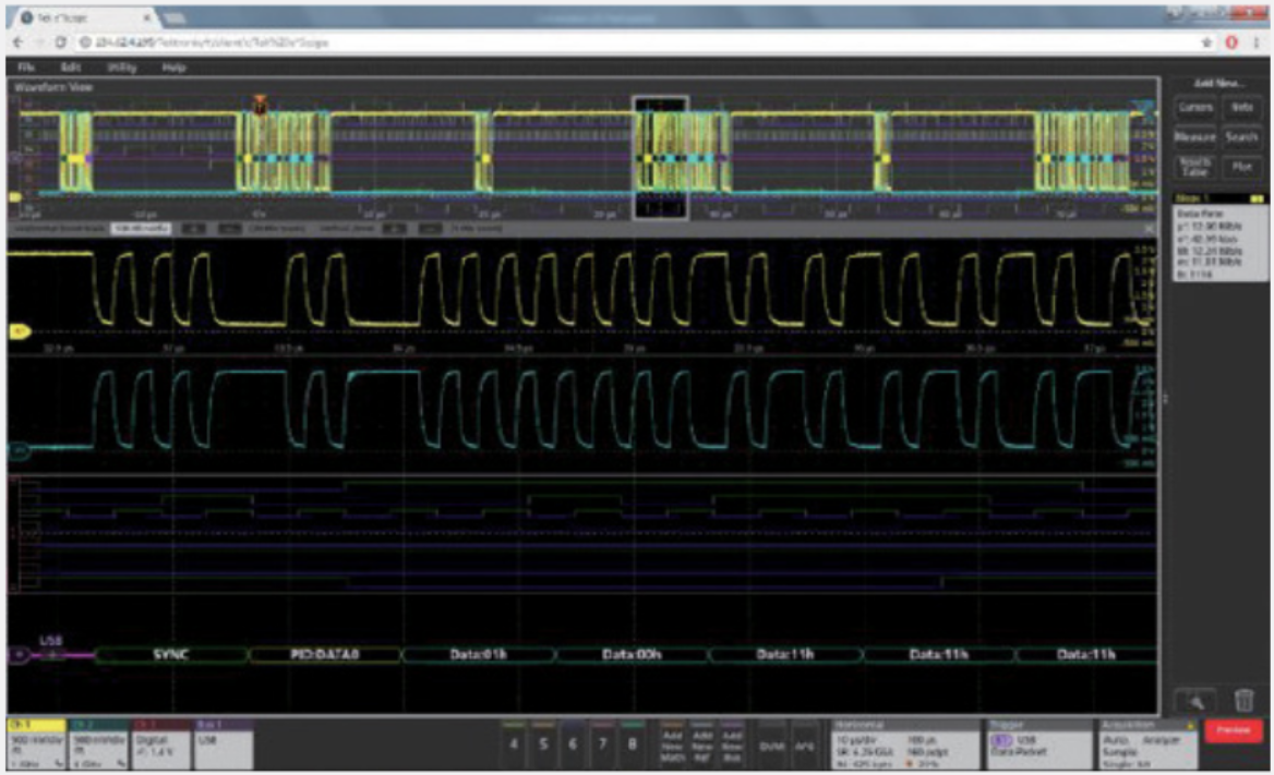
Connectivity
Every instrument includes a USB port and LXI-compliant Ethernet port for remote control. A thoroughly documented programming interface supports custom programming.
With e*Scope built-in, you can control the oscilloscope over a network through a standard web browser.
3, 4, 5, 6
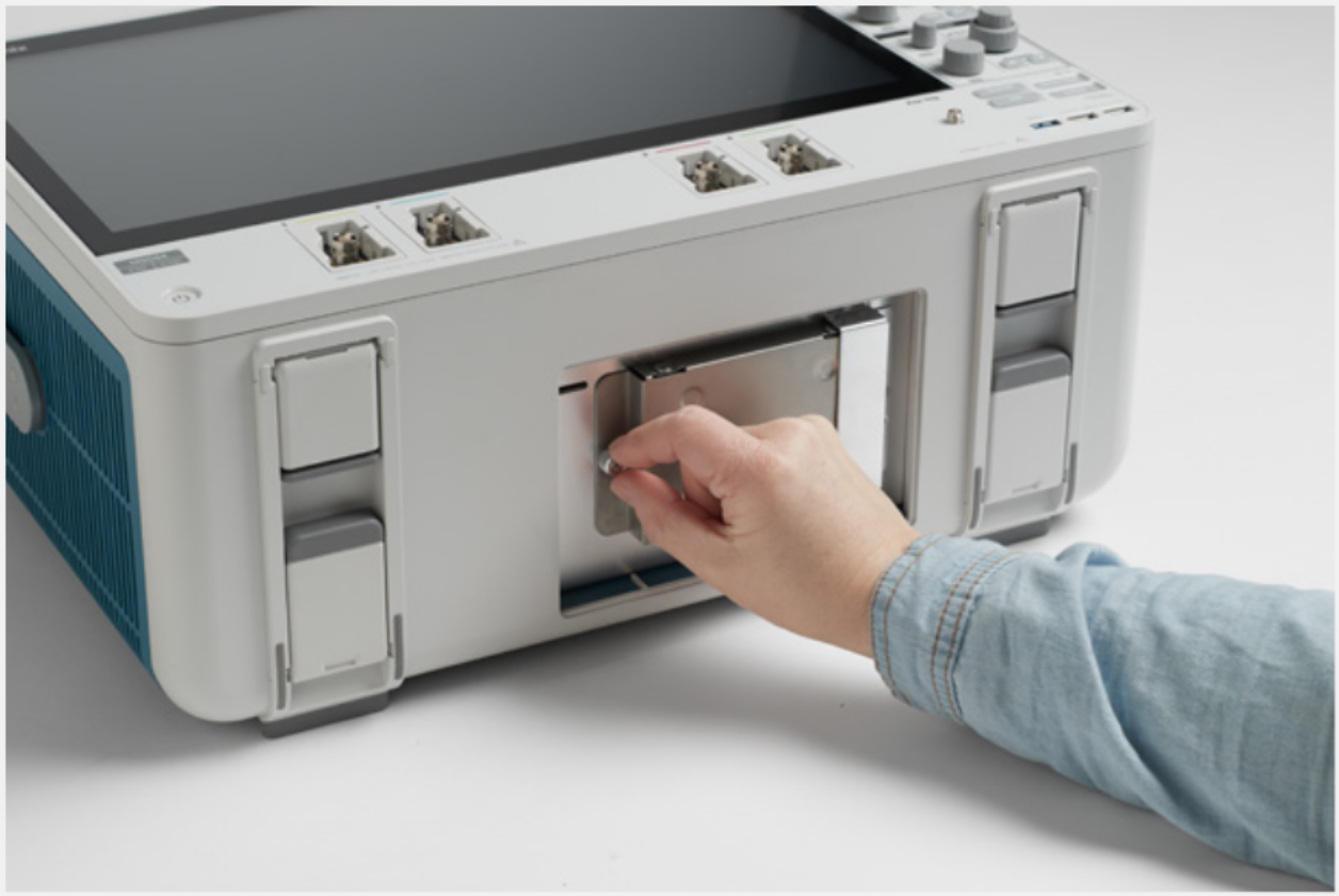
Optional Windows OS
The 5 and 6 Series MSOs offer the option of including a Microsoft Windows™ operating system. The option provides a Windows desktop where you can install and run additional applications on the oscilloscope.
Upgrading to Windows is as simple as plugging in a pre-configured SSD.
5, 6
Applications and Advanced Analysis. Emphasis on Analysis.
Built-in features, available probes, and optional analysis packages support a wide range of applications.
3, 4, 5, 6
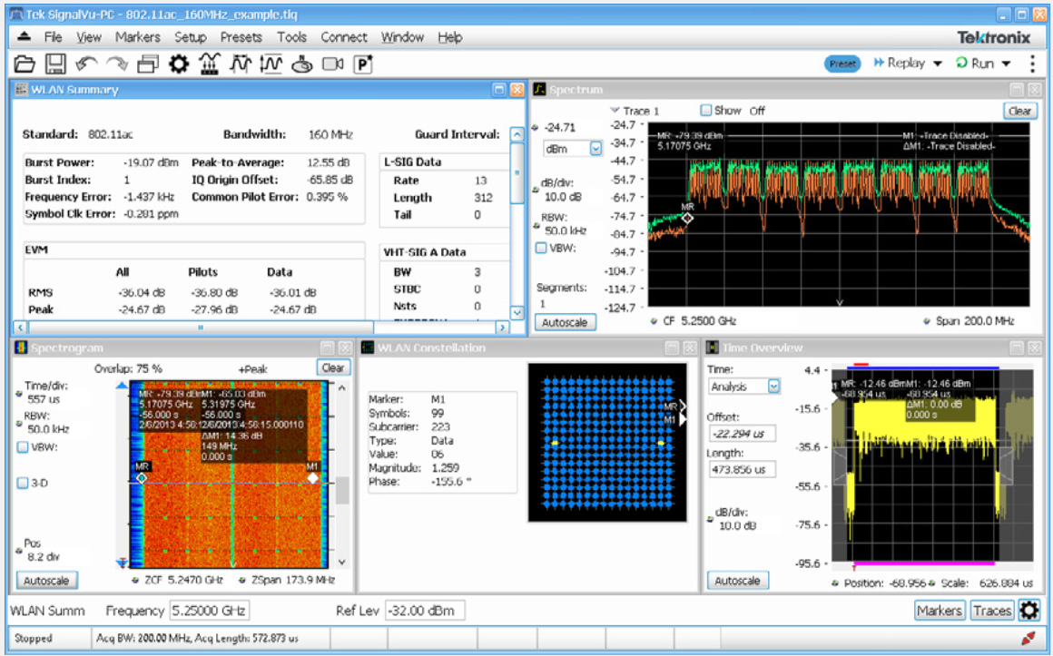
SignalVu-PC Vector Signal Analysis
SignalVu-PC turns your Windows-equipped 5 or 6 Series MSO into a wideband vector signal analyzer. It can be customized to suit your appplication.
- Perform RF measurements
- Demodulate and analyze RF signals
- Validate radar or pulsed RF
5, 6
Advanced Analysis
5, 6
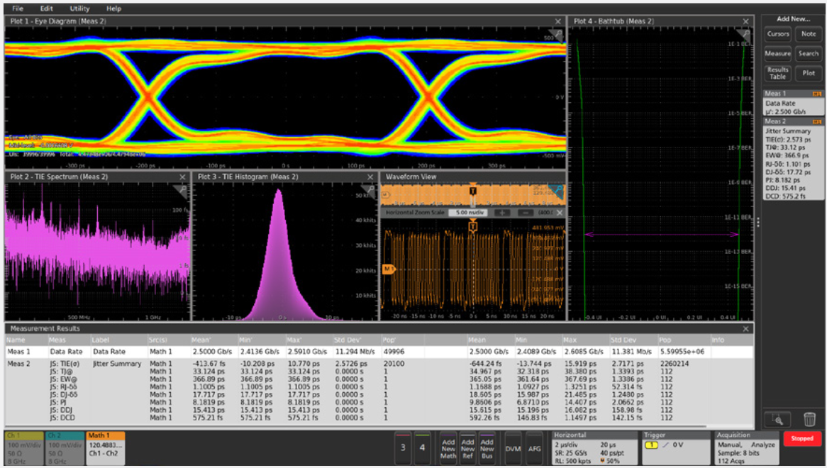
Jitter and timing analysis: Extended analysis functions such as eye diagrams and jitter analysis are optional.
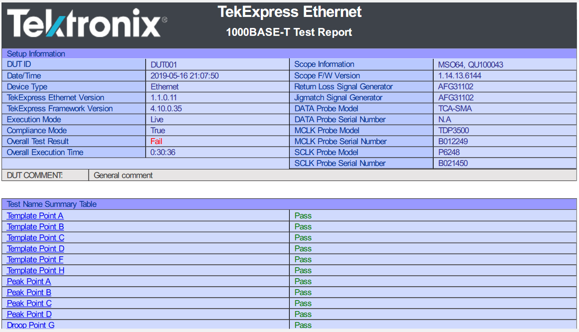
Automatic compliance test and debugging for popular serial standards.
Software
3, 4, 5, 6
TekScope PC Analysis Software
TekScope emulates the operation of a 4, 5 or 6 Series on your PC. The starter license lets you view and analyze waveforms, make measurements, remotely access your oscilloscope, and decode I2C, SPI and RS-232.
Advanced licenses add:
- Multi-scope waveform processing (4/5/6 Series)
- Serial bus decoding
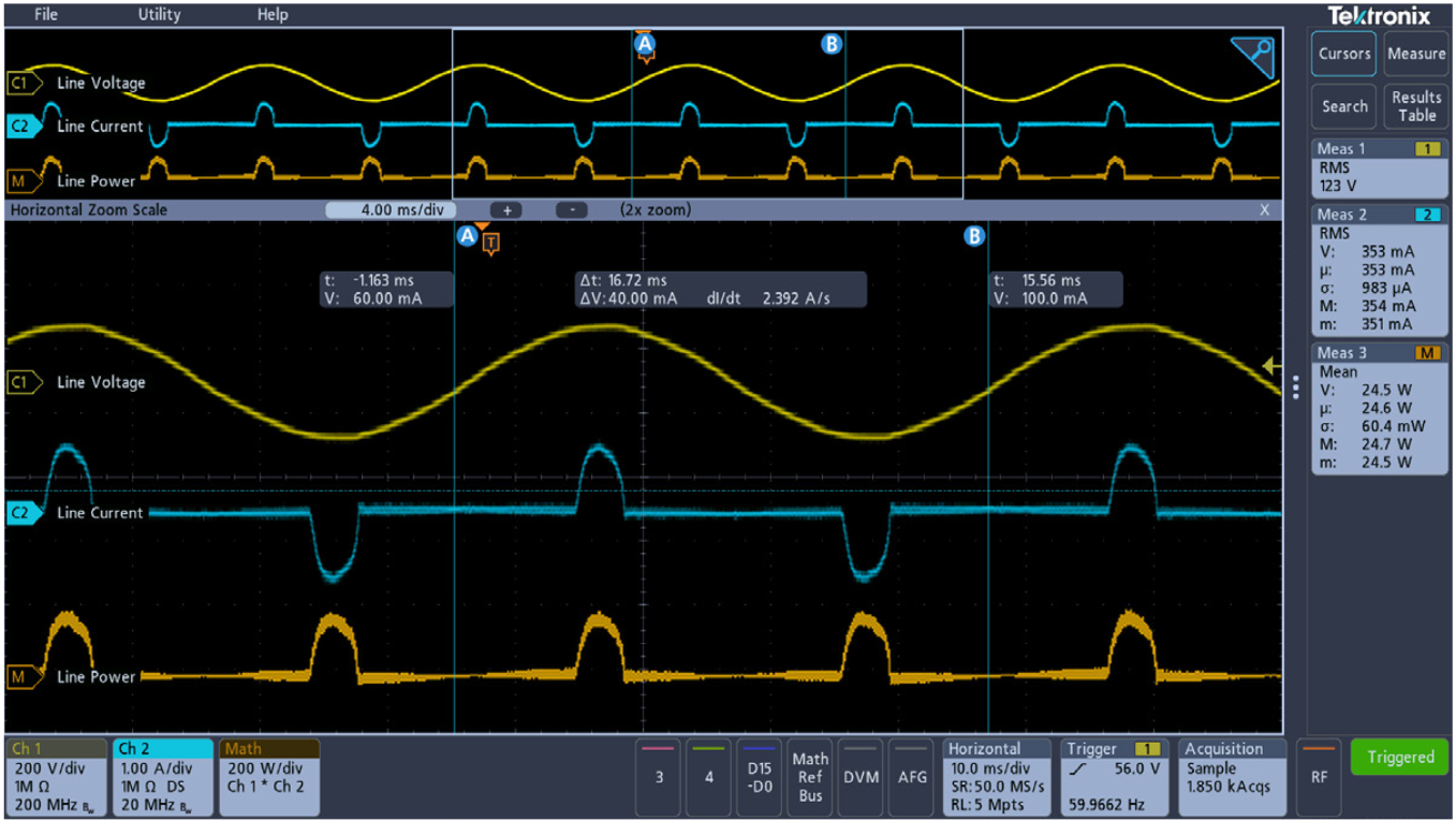
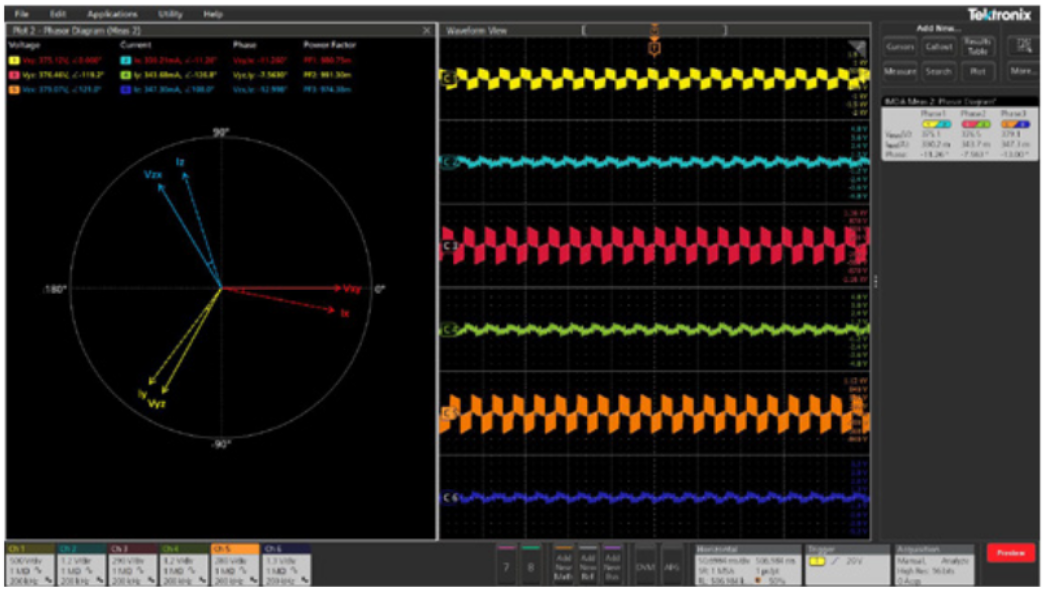
- Power analysis
- Automotive Measurements
- Aerospace Measurements

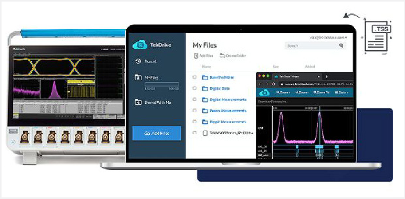
TekDrive
4, 5, 6
An oscilloscope-to-cloud software solution that facilitates data management and collaboration across oscilloscopes, PCs, smart phones, and tablets. On 4, 5 and 6 Series MSOs, TekDrive is accessible right from the Save/Recall controls. TekDrive also includes a well-documented API that enables integration with any software application for automation or analysis.
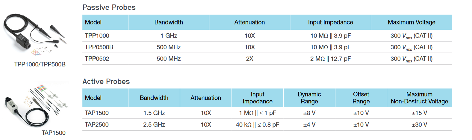
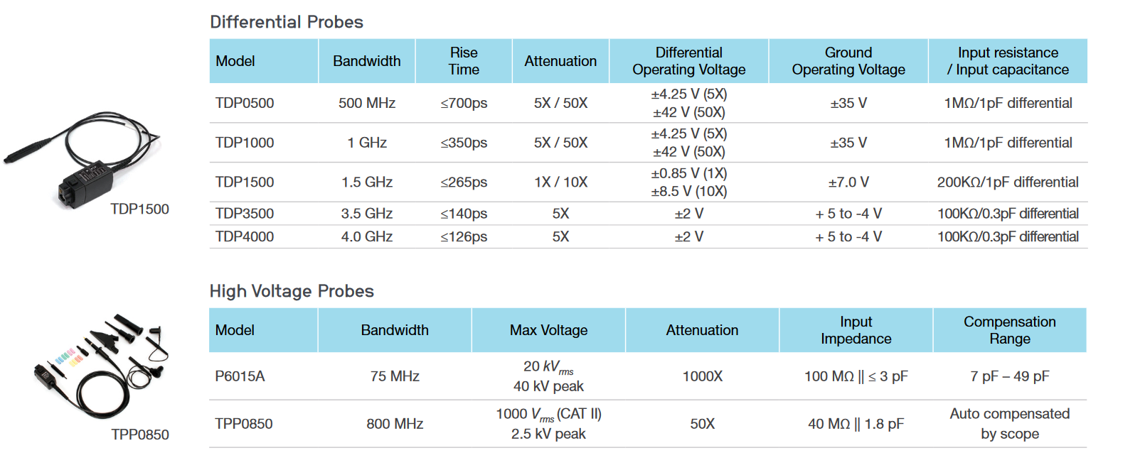
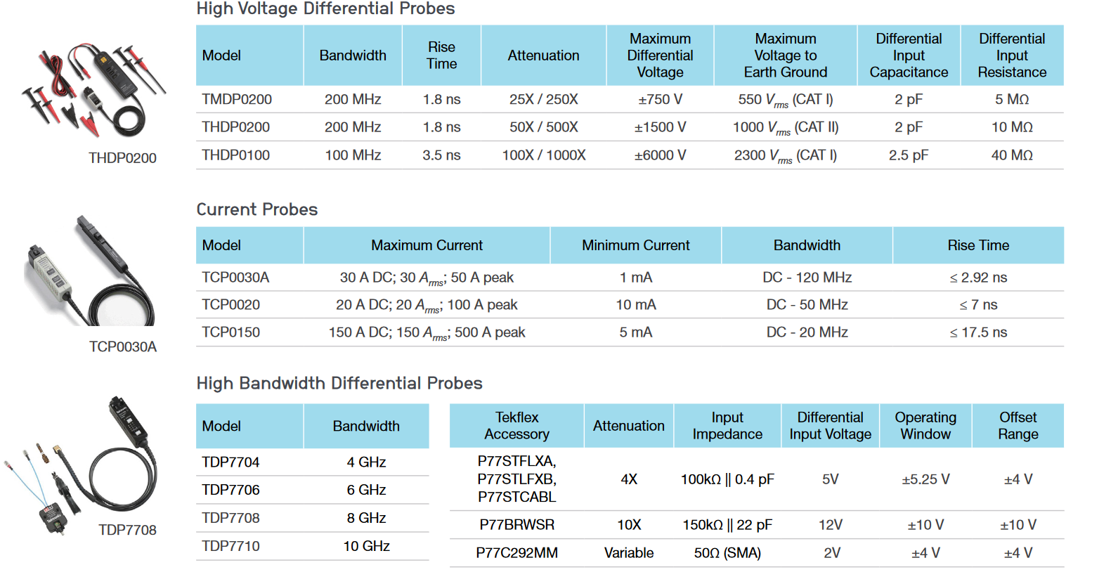
Probes
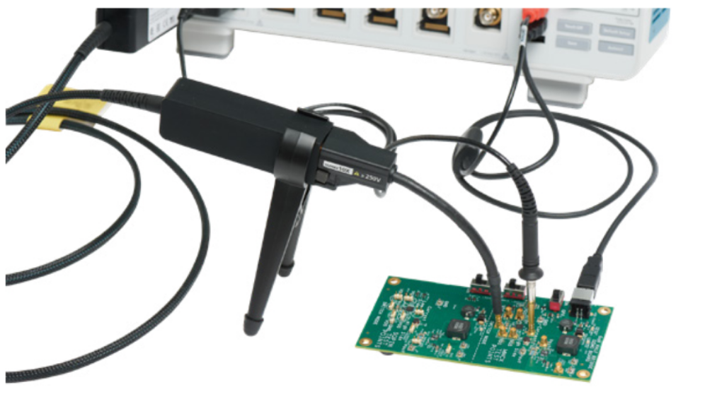
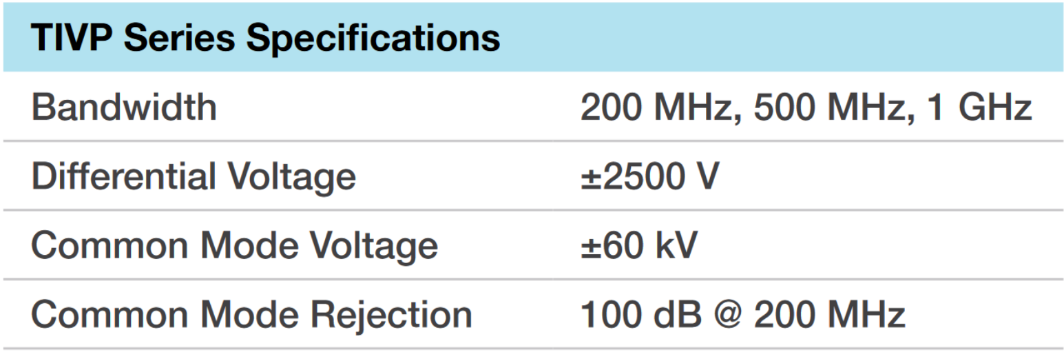
IsoVu™ Isolated Probes
IsoVu™ optical isolation technology virtually eliminates common mode interference for accurate differential measurements even with reference voltages slewing ±60 kV at 100 V/ns. Perfect for highside VGS measurements on GaN and SiC power converters.
4, 5, 6
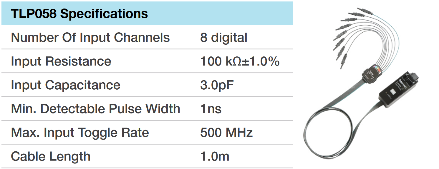
TLP058 Logic Probes
Have the right number of digital channels when you need them. Simply connect a TLP058 logic probe to any FlexChannel input and get 8 digital channels. Connect as many TLP058 probes you want.
4, 5, 6
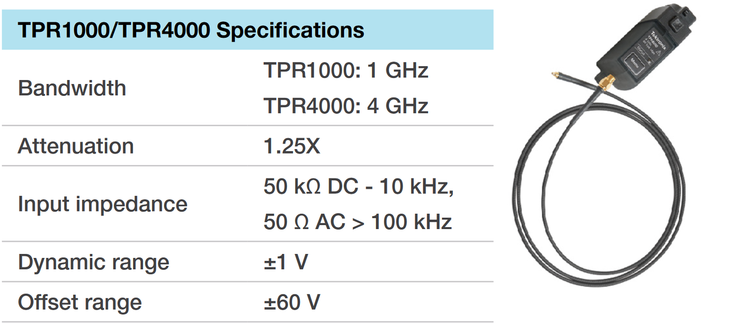
Power Rail Probes
Probes designed especially for making accurate ripple measurements on power rails, with ± 60 V DC offset range, low noise contribution and bandwidth up to 4 GHz.
4, 5, 6
For complete list of available probes visit tek.com/probes
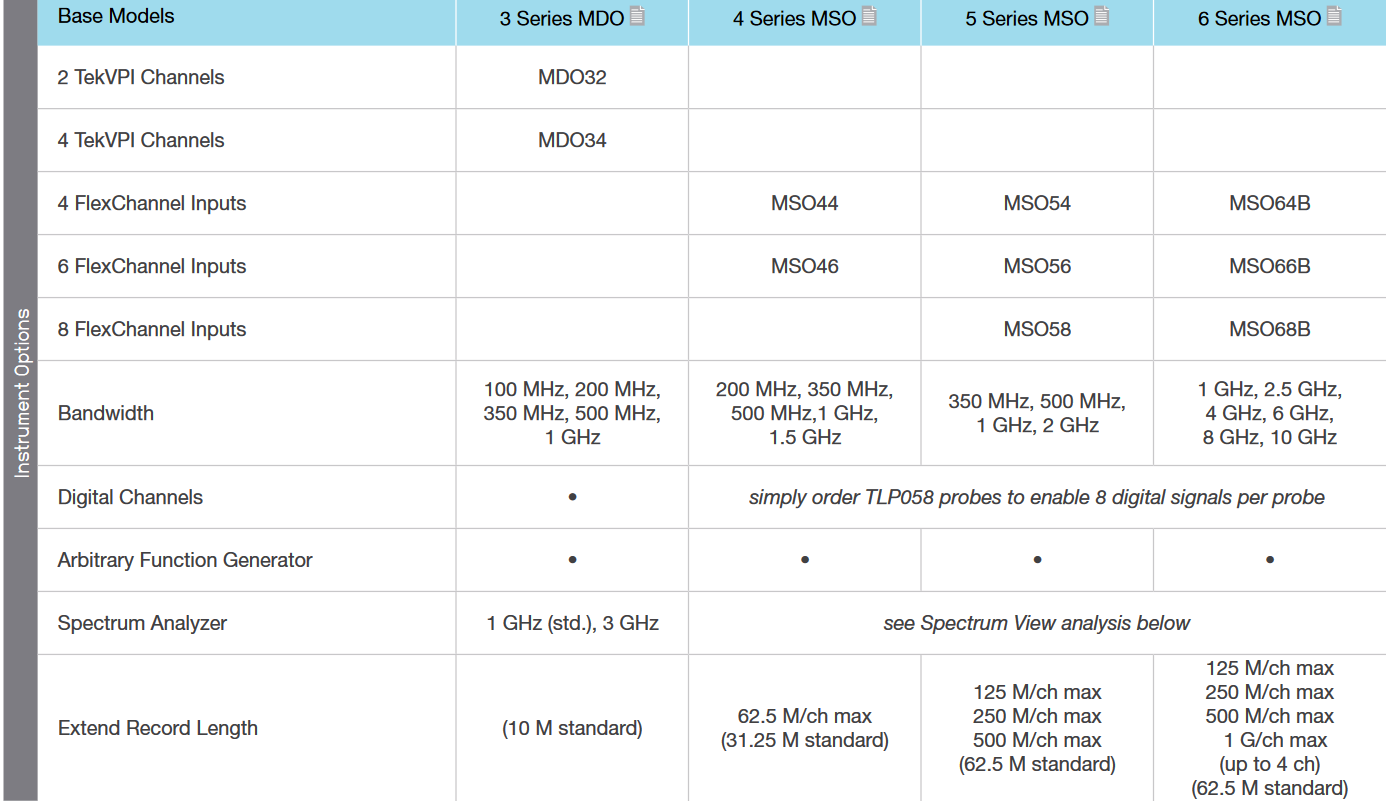
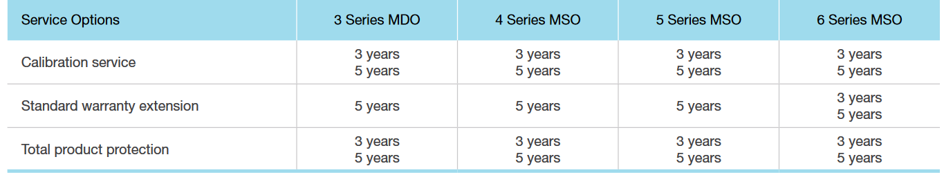
Models and Instrument Options
For complete ordering details see the product datasheet or contact your local sales representative.
Serial Bus Decoding, Compliance/Conformance Testing and Advanced Analysis
Listing of individual software options

High Speed Digitizers
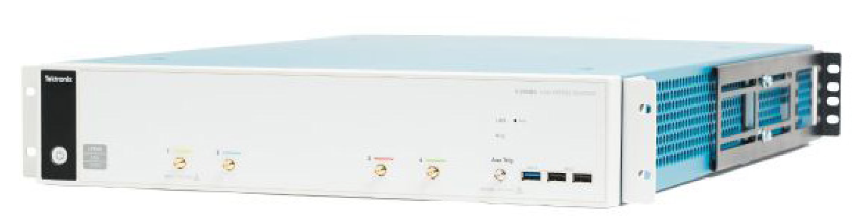
5 Series MSO Low Profile
The 5 Series MSO is available in a 2U low-profile form factor. Eight channels and 12-bit ADCs set a new standard when extreme channel density and measurement performance are required.
- 1 GHz bandwidth
- 6.25 GS/s sample rate
- 8 FlexChannel inputs
- Record length from 125 M to 500 M
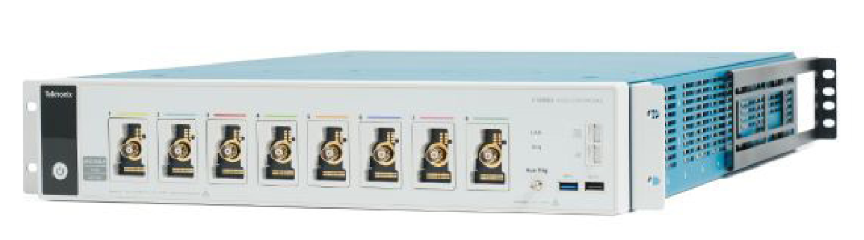
6 Series Low Profile Digitizer
The 6 Series Low Profile Digitizer sets a new standard for performance by not interleaving sample rate, bandwidth or record length. You get the fastest and most accurate performance from your digitizer – all in a 2U space.
- 1 GHz to 8 GHz bandwidth
- 25 GS/s sample rate
- 4 inputs
- Record length from 125 M to 1 G Test
Find more valuable resources at TEK.COM
Copyright © Tektronix. All rights reserved. Tektronix products are covered by U.S. and foreign patents, issued and pending. Information in this publication supersedes that in all previously published material. Specification and price change privileges reserved. TEKTRONIX and TEK are registered trademarks of Tektronix, Inc. All other trade names referenced are the service marks, trademarks or registered trademarks of their respective companies.
0122 48W-61573-4